
| PIN | I/O | Function | Range |
|---|---|---|---|
| 1 | I | Power+ | 7 – 30 V |
| 2 | I | Ground | 0 V |
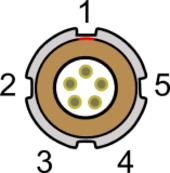
| PIN | I/O | Function | Range |
|---|---|---|---|
| 1 | O | RS232 Tx (PORT B) | +/- 12 V |
| 2 | I | RS232 Rx (PORT B) | +/- 12 V |
| 3 | I/O | CAN High (PORT A) | |
| 4 | I/O | CAN Low (PORT A) | |
| 5 | O | +V Power | Same as Power + |
| PIN | I/O | Function | Range |
|---|---|---|---|
| 1 | O | RS232 Tx (PORT B) | +/- 12 V |
| 2 | I | RS232 Rx (PORT B) | +/- 12 V |
| 3 | I/O | CAN High (PORT A) | |
| 4 | I/O | CAN Low (PORT A) | |
| 5 | O | +V Power | Same as Power + |
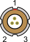
| PIN | I/O | Function | Range |
|---|---|---|---|
| 1 | I | Ground | |
| 2 | I | Digital Input 1 - Logging on/off | 0 – 5 V (14 V tolerant) |
| 3 | I | Digital Input - Event Marker | 0 – 5 V (14 V tolerant) |
| PIN | I/O | Function | Range |
|---|---|---|---|
| 1 | O | RS232 Tx (PORT B) | +/- 12 V |
| 2 | I | RS232 Rx (PORT B) | +/- 12 V |
| 3 | I/O | CAN High (PORT A) | |
| 4 | I/O | CAN Low (PORT A) | |
| 5 | O | +V Power | Same as Power + |
| PIN | I/O | Function | Range |
|---|---|---|---|
| 1 | O | RS232 Tx (PORT A) | +/- 12 V |
| 2 | I | RS232 Rx (PORT A) | +/- 12 V |
| 3 | I/O | CAN High (PORT B) | |
| 4 | I/O | CAN Low (PORT B) | |
| 5 | O | +V Power | Same as Power + |

| PIN | I/O | Function |
|---|---|---|
| Center | - | RF Signal / Power for active antenna |
| Chassis | - | Ground |
| PIN | I/O | Function |
|---|---|---|
| Center | - | RF Signal / Power for active antenna |
| Chassis | - | Ground |
NOTE
A screw terminal connector block is available to purchase on request from your VBOX supplier.
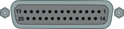
| PIN | In / Out | Description | Range |
|---|---|---|---|
| 1 | I | Isolated Channel 1 + | 1.8 M Ohms input impedance |
| 2 | I | Isolated Channel 1 - | 1.8 M Ohms input impedance |
| 3 | I | Isolated Channel 2 + | 1.8 M Ohms input impedance |
| 4 | I | Isolated Channel 2 - | 1.8 M Ohms input impedance |
| 5 | I | Isolated Channel 3 + | 1.8 M Ohms input impedance |
| 6 | I | Isolated Channel 3 - | 1.8 M Ohms input impedance |
| 7 | I | Isolated Channel 4 + | 1.8 M Ohms input impedance |
| 8 | I | Isolated Channel 4 - | 1.8 M Ohms input impedance |
| 9 - 10 | N/C | ||
| 11 | O | 1PPS Output | -IMU04 |
| 12 | O | RS232 TxD | -IMU04 |
| 13 | I | RS232 RxD | -IMU04 |
| 14 | O | Vbatt | Equal to Input Voltage. 300 mA |
| 15 | O | GND | Ground |
| 16 | O | 5 V Out | Isolated 5 V ±2%. 120 mA |
| 17 | O | GND | Ground |
| 18 | O | ISO-GND | Isolated Ground |
| 19-25 | N/C | ||