You can find more information about the different inputs and outputs here.
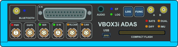
| BLUETOOTH | VBOX 3i ADAS comes equipped with a Bluetooth radio allowing configuration of the VBOX unit remotely along with remote output of real-time VBOX serial data, at the full 100 Hz data rate, to any Bluetooth capable PC or data logger. |
|---|---|
| A IN | This is the analogue input connector. Each of the four analogue input channels on VBOX 3i ADAS has a dedicated analogue converter. Data is recorded from each channel simultaneously to avoid latency between analogue channel data. The analogue input connector also provides two power outputs that may be used for driving sensors. |
| PWR | This is the power connector. VBOX 3i ADAS can accept a supply voltage between 7 and 30 V DC. Low current consumption results in extended battery life. |
| DGPS | The RS232 port named DGPS is designated for connection to a DGPS radio, allowing the reception of Differential GPS (DGPS) data for local correction. |
| SER | The primary RS232 port is used for all communication between the VBOX 3i ADAS unit and a laptop PC. The primary port is marked SER on the front panel of the VBOX 3i ADAS. In ADAS mode you can use this port with an ADAS radio. |
| D IN |
The ‘D IN’ connector contains the two digital inputs for the VBOX 3i ADAS.
|
| RLCAN | This connector is termination-enabled and is to be used with Racelogic modules and devices. |
| CAN | The CAN port is used for Racelogic CAN output and for logging third-party CAN data to the .vbb file. |
| AUDIO | VBOX 3i ADAS can record audio tags synched with a set GNSS timestamp, with an accuracy of 0.5 seconds. |
| USB | VBOX 3i ADAS includes a USB 2.0 connection that you can use to configure your VBOX unit and output real-time serial data at the full 100 Hz data rate |
| ANTENNA A | The primary antenna connector. |
| ANTENNA B | The secondary antenna connector. |
| CF | Indicates that the unit is writing to the Compact Flash card. |
|---|---|
| LOG | Indicates that the unit is capturing data to the CF card and the current logging rate. |
| SATS | Indicates the number of satellites being tracked. |
| DUAL | Indicates whether dual antenna mode is enabled/disabled and that antenna lock is fixed. |
| DIFF | Indicates the DGPS status. |
| IMU | Indicates the IMU integration and initialisation status. |
| BLUETOOTH | Indicates that communication has been initialised and that Bluetooth connection has been confirmed. |
| PWR | Indicates whether the unit is powered and ready to use or not. |
| SER | Indicates incoming serial traffic and that data has been decoded and is being logged. |
| D IN | Indicates activated/triggered event marker input. |
| RLCAN | Indicates that expected incoming CAN data has been decoded properly and is being logged. |
| CAN | Indicates that expected incoming CAN data has been decoded properly and is being logged. |
You can find the full description of the different behaviours of the LEDs here .
This is the CF Card slot on the front panel of the VBOX 3i unit. It accepts Type I compact flash cards to log data.
VBOX 3i units has two membrane buttons on the front panel, LOG and FUNC . LOG is used to start and stop logging to the compact flash card, and FUNC is used to switch between two sample rates, 100 Hz and 20 Hz.
The LOG button will override any of the automatic logging thresholds set in the VBOX unit. For example, if you have set the VBOX unit to log all the time, the LOG button will toggle logging on and off. If you have set the VBOX unit to ’log only when moving’ and you are moving, pressing the LOG button will stop the VBOX unit logging and close the file on the compact flash card. Logging will now not continue, even if you are moving, until you press the LOG button again or you remove the compact flash card and reinsert it. The VBOX unit will then continue to log only when moving.
NOTES
- If the VBOX unit is using ‘log only when moving’ log mode, and the vehicle has been stationary from power-up, the LOG button will not initiate logging. If you want the VBOX unit to log in this situation, you have to use VBOX Manager or VBOX Setup to change the log mode to ‘Log Continuous’.
- Every time the logging is toggled with the LOG button, a new file is created.
- When the VBOX unit is logging, the green LOG LED will be solid and the blue CF light will flash.
Press and hold the LOG button for 5 seconds to initiate a coldstart.
IMPORTANT
Do not remove the CF card or power down the unit while the CF LED is flashing. If you need to remove the card or power down the unit and the CF LED is flashing, you must press the LOG button first to manually stop the VBOX unit from logging. If you don't do this you can lose the data or corrupt the card.
Pressing the FUNC button briefly flashes the LOG LED and beeps to indicate the current sample rate. A slow flash (once per second) indicates 20 Hz, and rapid flash (5 times a second) indicates a 100 Hz sample rate. Pressing and holding the FUNC button for 5 seconds toggles the log rate between 20 Hz and 100 Hz. The sample rate can also be set using VBOX Manager or VBOX Setup.
You can restore the default factory settings on VBOX 3i unit by pressing and holding the FUNC and LOG buttons simultaneously for 10 seconds. This will trigger the reset process. There will be an audible notification beep and tune playing when the process has completed.