This page provides connection information for using an IMU04 with compatible VBOX data loggers.
Select the relevant VBOX product below to view the required equipment, hardware connections, and any product-specific requirements.
Once the hardware has been connected, additional configuration, initialisation, and calibration steps are required before testing can begin.
- VBOX 4 unit
- GNSS antenna(s)
- Power cable/battery pack
- IMU04 unit
- RLCAB131 – VBOX - IMU connecting cable
- RLCAB042 - VBOX 4 PC USB A to USB B cable
- VBOX Setup Software
- RLCAB069L / RLCAB015L / RLACS182L - vehicle CAN bus cable (optional, for wheel speeds)
IMPORTANT
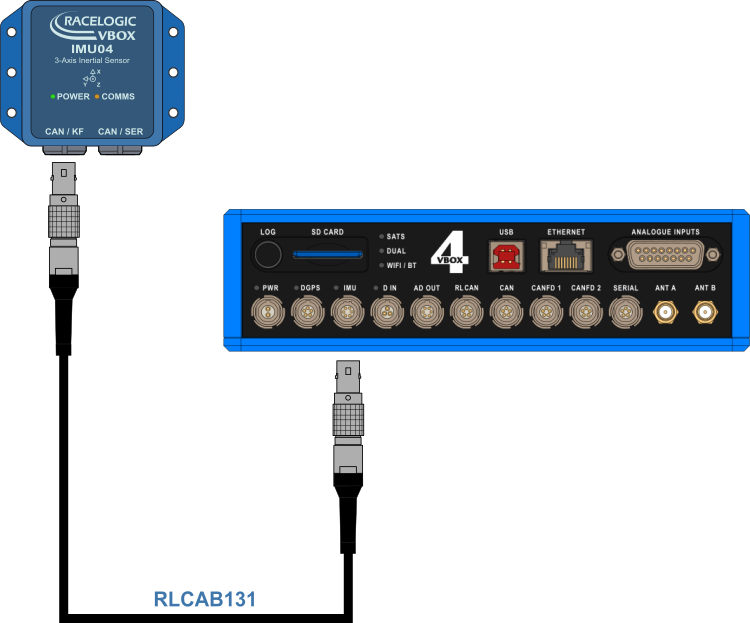
The IMU unit must be connected to the VBOX 4 unit before you apply power so that the data is synchronised correctly.
- Mount/place the VBOX 4 ADAS in the test vehicle, and mount the IMU as described on the Mounting page.
- Fit the VBOX 4 GNSS antenna to the centre of the vehicle's roof.
- Connect the antenna to the VBOX 4 unit.
- Connect the RLCAB131 cable between the CAN/KF port on the IMU04 and the IMU port on the VBOX 4 unit.
- Apply power to the VBOX 4 unit.
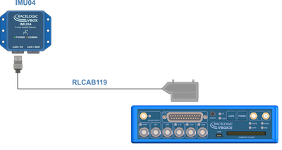
- VBOX 3i ADAS
- IMU04
- RLCAB119 – VBOX to IMU connecting cable
- RLCAB001/RLCAB066-2 – VBOX 3i PC connection cable
- VBOX Setup Software
- RLCAB069L / RLCAB015L / RLACS182L - vehicle CAN bus cable (optional – for wheel speeds)
IMPORTANT
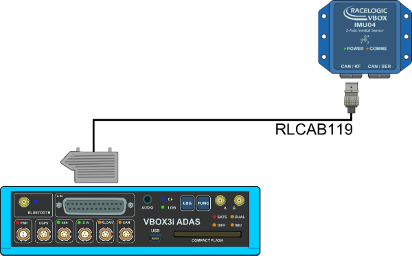
The IMU04 must be connected to the VBOX 3i ADAS before you apply power to make the data synchronise correctly.
- Install the VBOX 3i ADAS in the test vehicle, and mount the IMU as described on the Mounting page.
- Connect the required GPS/GNSS antenna(s) to VBOX 3i ADAS and place it/them on the vehicle roof.
Refer to the GNSS Antenna Placement and Setup page for more information. - Connect the LEMO connector on the RLCAB119 cable to the CAN/KF port on the IMU unit.
- Connect the analogue input connector on the RLCAB119 to the analogue input (A IN) port on the VBOX 3i unit.
- Apply power to the VBOX 3i unit.
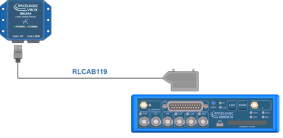
- VBOX 3i RTK
- VBOX 3i Dual Antenna
- VBOX 3i Single Antenna
- VBOX 3i unit (with firmware version 3.0 or later)
- GNSS antenna(s)
- Power Cable/Battery pack
- IMU04 unit
- RLCAB119 – VBOX - IMU connecting cable
- RLCAB001 / RLCAB066-2 - VBOX 3i PC connection cable
- VBOX Setup
- VBOX Manager (optional)
- RLCAB069L / RLCAB015L / RLACS182L - vehicle CAN bus cable (optional – for wheel speeds)
IMPORTANT
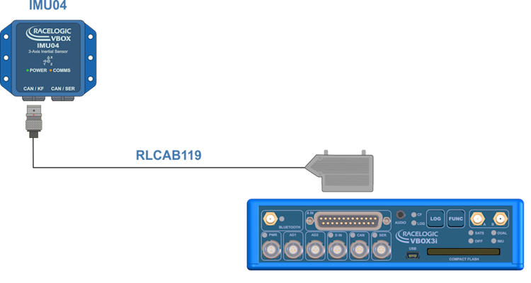
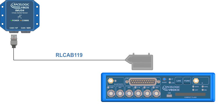
IMU04 must be connected to VBOX 3i before power is applied to ensure data is correctly synchronised.
- Place the VBOX 3i unit in the test vehicle, and mount the IMU as described on the Mounting page.
- Connect the required GPS/GNSS antenna(s) to VBOX 3i and place it/them on the vehicle roof.
Refer to the GNSS Antenna Placement and Setup page for more information. - Connect the LEMO connector on the RLCAB119 cable to the CAN/KF port on the IMU unit.
- Connect the analogue input connector on the RLCAB119 to the analogue input port on the VBOX 3i unit.
- Apply power to the VBOX 3i unit.
Additional configuration, initialisation and calibration processes are required before an IMU can be used.
Configure the IMU settings in VBOX Setup after installation.
The IMU must also complete initialisation and Kalman Filter Calibration before testing.
For more information, see the IMU Integration page.
IMPORTANT
- To use IMU04 integration, you must use an IMU-enabled VBOX 3i unit with firmware version 2.8 or later.
- IMU04 cannot be used with IMU integration if it is connected to a VBOX via CAN (RLCAB120/RLCAB005-CS). This method of connection will only allow standard IMU channels to be logged.