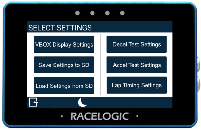
Access the MFD Touch Settings by tapping the Settings button in the footer.
This opens the Select Settings screen with the following options:
- VBOX Display Settings
- Decel Test Settings
- Accel Test Settings
- Lap Timing Settings
- Save Settings to SD
- Load Settings from SD
Tap on an option to open the relevant settings.
Most settings have multiple settings screens. Swipe left or right, or use the navigation buttons, to move between them.
Tap the currently selected option to change a setting.
Tap Exit to return to the display screen.

IMPORTANT
If you have an SD card inserted, the display will remember settings values between each use and open the last used screen when it starts again. If you do not have an SD card inserted, MFD Touch will boot using the default settings.
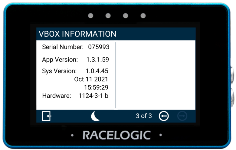
The unit's General Settings contain measurement units, brightness, average speed calculation, reset and alert options, as well as unit information.
There are 3 General Settings screens:
- Units of Measurement / Screen Settings
- Data/Alerts
- VBOX Information
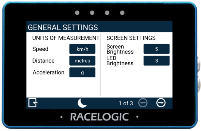
Speed
Allows you to change the speed units between km/h (default) and mph. Changing the speed units will affect all visual speed parameters on all screens, the unit labels will change, and all speed values and results will automatically be recalculated.

Allows you to change the speed units between km/h (default) and mph. Changing the speed units will affect all visual speed parameters on all screens, the unit labels will change, and all speed values and results will automatically be recalculated.

Distance
Change the distance units used on the display. The option are metres (default) and feet.
Changing the distance unit will affect all visual distance parameters on all screens. The unit labels will change, and all distance values and results will automatically be recalculated.

Change the distance units used on the display. The option are metres (default) and feet.
Changing the distance unit will affect all visual distance parameters on all screens. The unit labels will change, and all distance values and results will automatically be recalculated.

Acceleration
Allows you to change the acceleration units between g (default) and m/s². Changing the acceleration units will affect all acceleration references on all screens, the unit labels will change, and all acceleration values and results will automatically be recalculated. Tap the button to change the units.

Allows you to change the acceleration units between g (default) and m/s². Changing the acceleration units will affect all acceleration references on all screens, the unit labels will change, and all acceleration values and results will automatically be recalculated. Tap the button to change the units.

Screen Brightness
Adjust the screen brightness manually.
1 is the dimmest and 5 is the brightest.
Auto (default) uses the internal ambient light sensor to automatically adjust the screen brightness. In dark conditions, the screen brightness will dim, and in light conditions, the screen will brighten.
Tap the button to cycle through the available options.

LED Brightness
Adjust the LED brightness manually.
1 is the dimmest and 5 is the brightest.
You can also turn the LEDs off by setting this option to Disabled.
Tap the button to cycle through the available options and the LEDs will preview the brightness level as you do.
The default brightness level is 3.

Adjust the LED brightness manually.
1 is the dimmest and 5 is the brightest.
You can also turn the LEDs off by setting this option to Disabled.
Tap the button to cycle through the available options and the LEDs will preview the brightness level as you do.
The default brightness level is 3.

IMPORTANT
LED brightness level 5 is very bright and may cause glare or discomfort in low-light conditions.
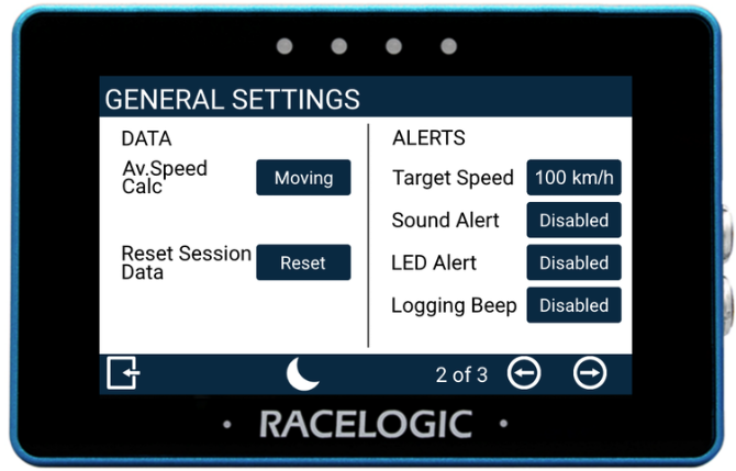
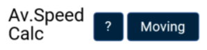
Average Speed Calculation
This setting determines how the average speed parameter data is calculated.
- Moving (default): Average speed will start to calculate as soon as a speed over 0.5 km/h is detected. Calculations will stop when the speed is less than 0.8 km/h.
- Continuous: Average speed is calculated continuously from the start of the test.
Reset Session Data
Tap this button to reset the results for the calculated average speed, maximum lateral acceleration and calculated distance travelled.
The LEDs will flash green and the unit will emit an audible confirmation notification.
VBOX Touch will display a Cancel Timeout screen, allowing you to cancel the reset within 5 seconds by tapping the screen.
If cancelled, the LEDs will flash red and the unit will emit an audible error note, notifying you that the reset has been cancelled.

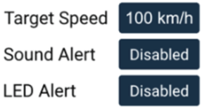
Target Speed Alert
Enable the display to alert you when a defined target speed is reached.
You can enable:
- Sound Alert – continuous beep for 2 seconds
- LED Alert – all four LEDs flash green
You can enable either alert or both.
The Target Speed option is only available when at least one alert is enabled.
Tap the current Target Speed value to enter a new speed. Confirm to save, or cancel to return without saving.
Alerts are triggered once per run. The alert resets when the vehicle is detected as stationary, and will trigger again when the target speed is reached.
The target speed is displayed beneath the speed value on the Speed, VMAX, and Average Speed screens.

Logging Beep
When enabled, the display will emit an audible alert when the logging state of the connected VBOX unit changes.
Different tones are used to indicate:
- logging start
- logging stop and paused logging (in Log When Moving mode)

When enabled, the display will emit an audible alert when the logging state of the connected VBOX unit changes.
Different tones are used to indicate:
- logging start
- logging stop and paused logging (in Log When Moving mode)

The Decel Test Settings configure deceleration tests and contains start/end, alerts, and MFDD options.
There are 2 Decel Test Settings screens:
- Decel Test Settings
- Decel Test Settings - Trigger Only
Refer to the Data Display Screen page for the list of available Decel Test parameters.
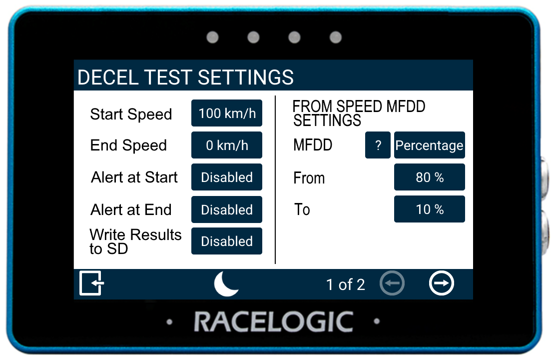
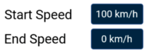
Start/End Speed
Define the start and end speed conditions of the deceleration test by tapping the corresponding buttons and using the presented keypad to enter the required speed values (max 999.9 with 1 decimal).

Define the start and end speed conditions of the deceleration test by tapping the corresponding buttons and using the presented keypad to enter the required speed values (max 999.9 with 1 decimal).
Alert at Start
Select to enable audible and visual alert signals when the decel test's start speed criteria are met. The unit will briefly beep and the 4 LEDs across the top of the device will flash green.

Select to enable audible and visual alert signals when the decel test's start speed criteria are met. The unit will briefly beep and the 4 LEDs across the top of the device will flash green.

Alert at End
Select to enable audible and visual alert signals when the decel test's end speed criteria are met. The unit will beep and the 4 LEDs across the top of the device will flash green.

Select to enable audible and visual alert signals when the decel test's end speed criteria are met. The unit will beep and the 4 LEDs across the top of the device will flash green.

Write Results to SD
Select this option to enable the Decel Test results to be written to an inserted SD card.
If VBOX Touch cannot detect an SD card:
- the unit will beep
- the 4 LEDs across the top of the device will flash red
- the unit will emit an audible tone
- a 'NO SD CARD' message will display

Select this option to enable the Decel Test results to be written to an inserted SD card.
If VBOX Touch cannot detect an SD card:
- the unit will beep
- the 4 LEDs across the top of the device will flash red
- the unit will emit an audible tone
- a 'NO SD CARD' message will display

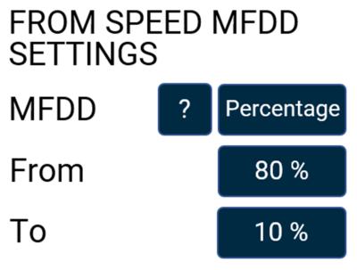
MFDD Settings
This area allows you to set up the start and end periods of the Mean Fully Developed Deceleration (MFDD) analysis period.
This deceleration figure is used to show the maximum deceleration figure a vehicle can achieve. It is usually the deceleration between 80% and 10% of the trigger activation speed, the time at which the vehicle is loaded up and braking at its highest achievable level.
Refer to the Mean Fully Developed Deceleration (MFDD) article for more information about MFDD.
Input Limits and Constraints
Speed-based configuration
- From: max = Start Speed, min = greater of 5 km/h or (To + 1)
- To: max = From − 1, min = End Speed (or 0 with brake trigger)
Percentage-based configuration
- From: max = 100%, min = To + 1
- To: max = From − 1, min = End Speed (% of Start Speed) or 0
Maximum input: 999.9 (1 decimal place).

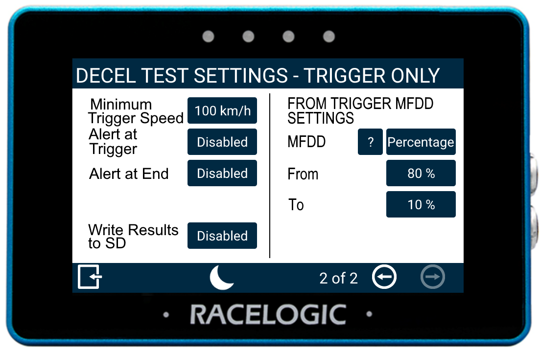
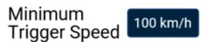
Minimum Trigger Speed
Define the minimum trigger speed at which trigger activation becomes valid. If the trigger is detected below this speed, the test will not start.
Change this value by pressing the current value and using the presented keypad.

Define the minimum trigger speed at which trigger activation becomes valid. If the trigger is detected below this speed, the test will not start.
Change this value by pressing the current value and using the presented keypad.
Alert at Trigger
Select to enable audible and visual alert signals when the decel test's trigger test has started. The unit will briefly beep and the 4 LEDs across the top of the device will flash green.

Select to enable audible and visual alert signals when the decel test's trigger test has started. The unit will briefly beep and the 4 LEDs across the top of the device will flash green.

Alert at End
Select to enable audible and visual alert signals when the decel test's end speed criteria are met. The unit will beep and the 4 LEDs across the top of the device will flash green.
Select to enable audible and visual alert signals when the decel test's end speed criteria are met. The unit will beep and the 4 LEDs across the top of the device will flash green.
Write Results to SD
Select this option to enable the Decel Test results to be written to an inserted SD card.
If VBOX Touch cannot detect an SD card:
- the unit will beep
- the 4 LEDs across the top of the device will flash red
- the unit will emit an audible tone
- a 'NO SD CARD' message will display
Select this option to enable the Decel Test results to be written to an inserted SD card.
If VBOX Touch cannot detect an SD card:
- the unit will beep
- the 4 LEDs across the top of the device will flash red
- the unit will emit an audible tone
- a 'NO SD CARD' message will display
MFDD Setting
This area allows you to set up the start and end periods of the Mean Fully Developed Deceleration (MFDD) analysis period.
This deceleration figure is used to show the maximum deceleration figure a vehicle can achieve. It is usually the deceleration between 80% and 10% of the trigger activation speed, the time at which the vehicle is loaded up and braking at its highest achievable level.
Refer to the Mean Fully Developed Deceleration (MFDD) article for more information about MFDD.
Input Limits and Constraints
Speed-based configuration
- From: max = Start Speed, min = greater of 5 km/h or (To + 1)
- To: max = From − 1, min = End Speed (or 0 with brake trigger)
Percentage-based configuration
- From: max = 100%, min = To + 1
- To: max = From − 1, min = End Speed (% of Start Speed) or 0
Maximum input: 999.9 (1 decimal place).
The Accel Test Settings configure acceleration tests and contains start/end, alerts, and 1-ft rollout options.
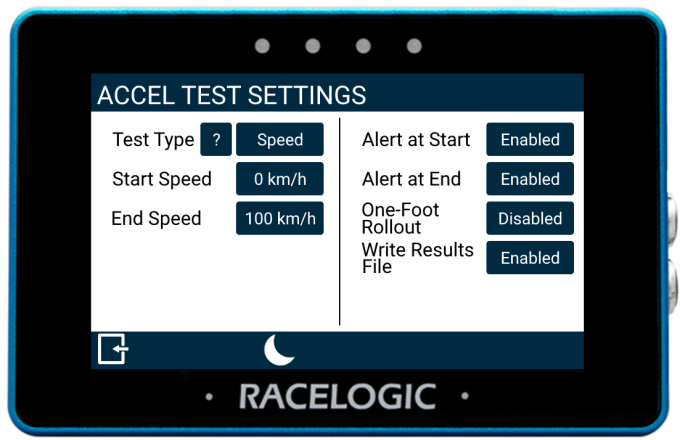
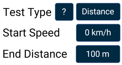
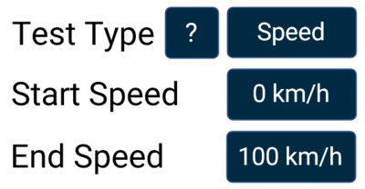
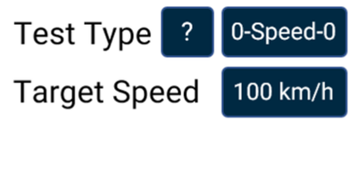
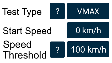
Test Type
Tap the Test Type button to cycle through the available acceleration tests:
- Speed
- Distance
- 0-Speed-0
- VMAX
Each test type measures a different aspect of vehicle performance.
Tap the ? icon for more information about each test type.
The configurable parameters will update based on the selected test.
Define the test parameters by tapping the current values to enter new values using the on-screen keypad.
Confirm the values to apply the setting, or cancel to return without saving.


| Test Type | Parameter | Minimum Value | Maximum Value | Notes |
|---|---|---|---|---|
| Speed | Start Speed (km/h or mph) | 0 | 998.9 | -- |
| End Speed (km/h or mph) | >5 km/h and Start + 1 | 998.9 | -- | |
| Distance | Start Speed (km/h or mph) | 0 | 998.9 | -- |
| End Distance (m or ft) | 1 | 99999 | -- | |
| 0-Speed-0 | Target Speed (km/h or mph) | 5 km/h | 998.9 | -- |
| VMAX | Start Speed (km/h or mph) | 0 | 998.9 | If <1, starts from stationary |
| Speed Threshold (km/h or mph) | 0 | 999.9 | Ends when speed exceeds threshold and acceleration stops |
Alert at Start
Enable audible and visual alerts when the accel test start speed is reached.
The unit will briefly beep, and the four LEDs across the top of the device will flash green to indicate the test has started.
Enable audible and visual alerts when the accel test start speed is reached.
The unit will briefly beep, and the four LEDs across the top of the device will flash green to indicate the test has started.
Alert at End
Enable audible and visual alerts when the accel test end speed is reached.
The unit will beep, and the four LEDs across the top of the device will flash green to indicate the test has completed.
Enable audible and visual alerts when the accel test end speed is reached.
The unit will beep, and the four LEDs across the top of the device will flash green to indicate the test has completed.
One-Foot Rollout
When enabled, tests will only start once the vehicle has travelled 1 ft (0.305 m).

When enabled, tests will only start once the vehicle has travelled 1 ft (0.305 m).

IMPORTANT
“ONE FOOT ROLLOUT ENABLED” will be added to each logged test result on the SD card.
Write Results to SD
Enable logging of accel test results to an inserted SD card.
Enable logging of accel test results to an inserted SD card.
WARNING
If the unit cannot detect an SD card, results will not be saved.
The unit will:
- beep
- flash the four LEDs across the top of the device red
- display a “NO SD CARD” message
The Lap Timing settings configure start and finish gates and splits for lap timing purposes.
There are 2 Lap Timing Settings screens:
- Lap Timing Settings - Gate Survey
- Lap Timing Settings
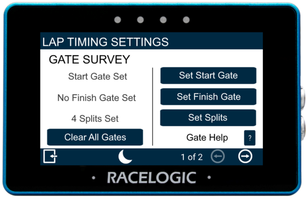
Clear All Gates
Clears all active lap timing gates.
Selecting this option begins the clearing process and displays a progress screen. Tap the screen before the process completes to abort and keep the current gates.
IMPORTANT
Once the process completes, all lap timing gates are permanently removed.
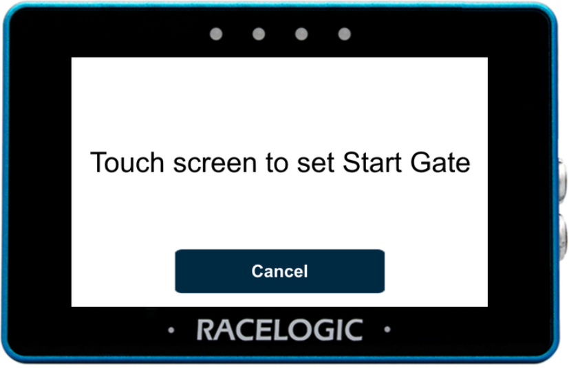
Set Start Gate
Tap the Set Start Gate button to open the Set Start Gate screen.
Drive to the required location on the track, then tap the screen to set the start gate.
The start gate is used as both the start and finish gate by default. Set a separate finish gate only if required.
Select Cancel to return to the Lap Timing Settings without setting a gate.
IMPORTANT
The vehicle must be moving for this function to be available, as the system requires a heading to set the gate.
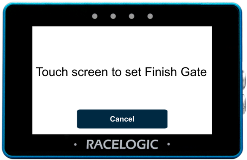
Set Finish Gate
Tap the Set Finish Gate button to open the Set Finish Gate screen.
Drive to the required location on the track, then tap the screen to set the finish gate.
Select Cancel to return to the Lap Timing Settings without setting a gate.
IMPORTANT
If a separate finish gate is not set, the start gate will also be used as the finish gate.
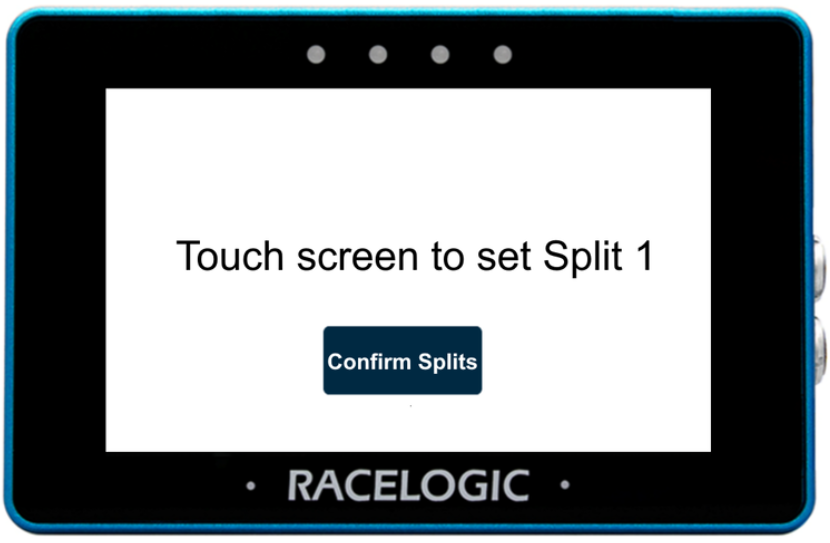
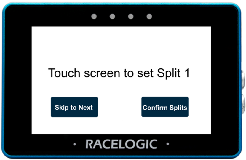
Set Splits
You can set up to 6 splits for lap timing.
Drive to the required location on the track, then tap the screen to set a split. The screen will automatically change to set the next split. Tap the screen again when you want to add the next split.
Select Confirm Splits at any time to save the configured splits and return to the Lap Timing Settings.
Edit Splits
Once splits have been created, you can return and edit them.
You can:
- add additional splits (up to a maximum of 6)
- change the location of existing splits
Use the Skip to Next button to move past splits you want to keep. When the required split is shown, tap the screen to set the split at the vehicle's current location.
Select Confirm Splits at any time to save the configured splits and return to the Lap Timing Settings.
Gate Help
Select the ? button to view help for start/finish and split gates.

Select the ? button to view help for start/finish and split gates.

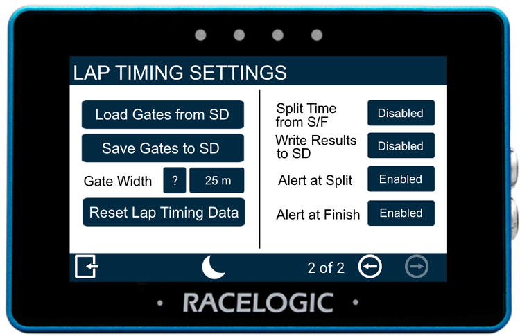
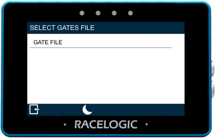
Load Gates from SD
Import gates from a gates file stored on the inserted SD card.
Selecting this option opens the Select Gates File screen, where you can choose from the available files.
Save Gates to SD
Save the configured start/finish and split gates to a gates file on the SD card.
Selecting this option begins the save process. Tap the screen while the file is being saved to abort.
Gate Width
The gate width is set to 25 m by default.
Tap the gate width value to enter a different width using the presented key pad.
Tap the ? button next to the gate width to view more information about this setting.

The gate width is set to 25 m by default.
Tap the gate width value to enter a different width using the presented key pad.
Tap the ? button next to the gate width to view more information about this setting.

Reset Lap Timing Data
Clears cumulative and historical lap timing results, including:
- average lap time
- lap count
- best lap time
Selecting this option begins the reset process and displays a progress screen.
Tap the screen before the process completes to abort and keep the current data.
IMPORTANT
Once the process completes, all lap timing data is permanently removed.
Split Time from S/F
Split time can be calculated either from the start gate or from the previous split gate. Use this setting to control how split time is reported.
Enabled – split time is calculated from the start gate crossing
Disabled – split time is calculated from the previous split gate crossing (split-to-split time)

Write Results to SD
Control whether lap timing results are written to the inserted SD card.
Enabled – results are saved to the SD card
Disabled – results are not saved
Control whether lap timing results are written to the inserted SD card.
Enabled – results are saved to the SD card
Disabled – results are not saved
Alert at Split
Enable alerts when defined split gates are crossed.
Enabled – the unit will beep and flash LEDs when a valid split gate is crossed during an active lap
Disabled – no alerts are triggered

Enable alerts when defined split gates are crossed.
Enabled – the unit will beep and flash LEDs when a valid split gate is crossed during an active lap
Disabled – no alerts are triggered

Alert at Finish
Enable alerts when an active lap is completed.
Enabled – the unit will beep and the LEDs will flash when a lap is completed
Disabled – no alerts are triggered

Enable alerts when an active lap is completed.
Enabled – the unit will beep and the LEDs will flash when a lap is completed
Disabled – no alerts are triggered

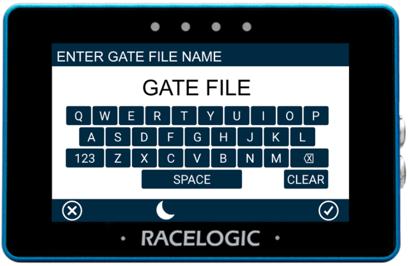
Save the current settings to an inserted SD card.
Tap Save Settings to SD and enter a file name using the on-screen keyboard.
Confirm to save, or cancel to return without saving.
WARNING
If the unit cannot detect an SD card, the settings will not be saved.
The unit will:
- display “NO SD CARD” in the screen header
- flash all four LEDs red twice
- emit an audible error tone
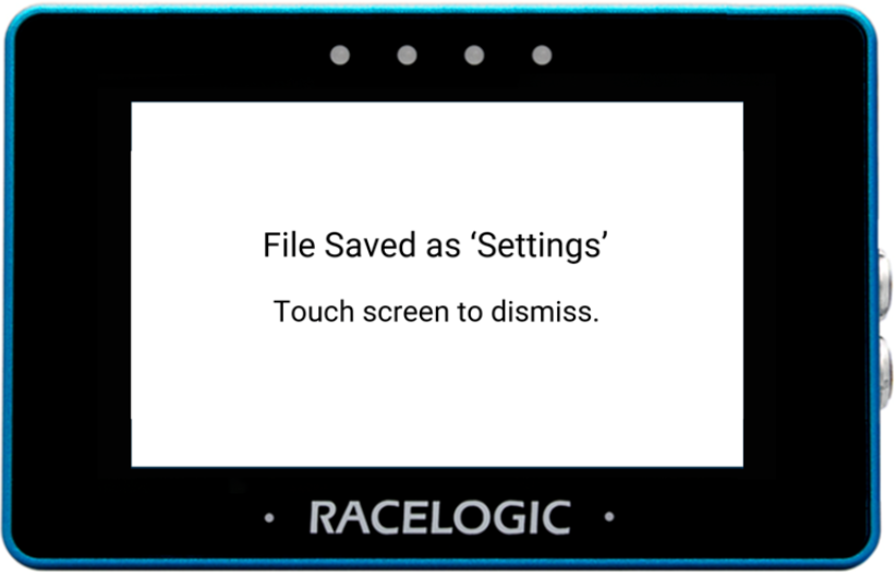
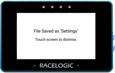
When a file is saved successfully, the unit will:
- display a File Saved notification
- flash the LEDs green
- emit a confirmation tone
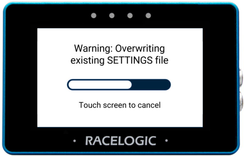
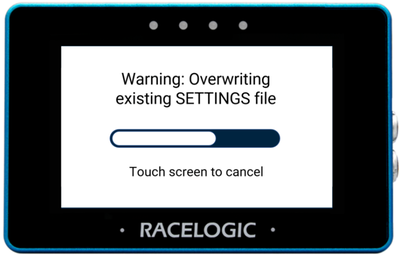
If a file with the same name already exists, the unit will warn that it will be overwritten.
A cancel timeout screen is displayed, allowing you to cancel the overwrite within 5 seconds.
If the overwrite is cancelled, the unit will:
- flash the LEDs red briefly
- emit an audible tone
Load a previously saved settings file from an inserted SD card.
Select Load Settings from SD, then choose the required file and confirm to load it.
When the file is loaded successfully, the unit will:
- display a File Loaded notification
- flash the LEDs green
- emit a confirmation tonegs file from an inserted SD card.
WARNING
If no SD card is detected, the settings cannot be loaded.
The unit will:
- display “NO SD CARD” in the screen header
- flash all four LEDs red twice
- emit an audible error tone