As the name suggests, MFD Touch is controlled by the capacitive touch screen.
Generally, the different areas of the screen contain the following:
- Top bar – indicative status information
- Main area – data display and settings information
- Bottom bar – function buttons
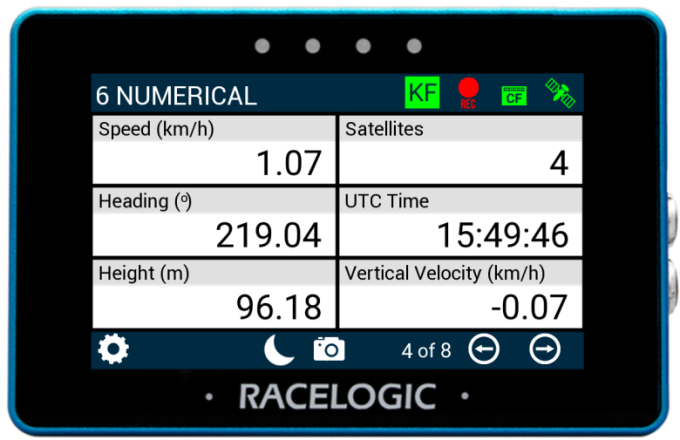
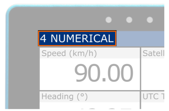
MFD Touch displays live data from the connected VBOX unit across multiple screen layouts.
- 8 different screen types are displaying different combinations of parameters and gauges.
- A screen can display up to 6 defined VBOX parameters, depending on the selected layout.
- You can add up to 10 screens at a time.
Each screen includes status indicators, a display area, and navigation controls.
The status indicators show information such as logging state, media status, and connection status, and the on-screen controls let you switch between display screens and navigate to the settings menus.
Add, remove and customise screens as required.
MFD Touch uses data display screens to present live data from the connected VBOX system.
Each screen contains one or more elements (such as gauges or numerical values), which display individual parameters, such as speed and distance.
- Swipe left or right to move between display screens.
- Long-press an element or parameter to access its settings.
See the Data Display Screens section for details on each screen type and available settings.
When the unit starts for the first time, the 6 numerical screen will be displayed by default.
Use the Add/Remove screen to manage the data display screens available on the MFD Touch.
Tap the navigation button(s) in the footer or swipe on the screen to access the Add/Remove screen before/after the available data display screen(s).
The name of the current Data Display Screen will be shown in the left corner of the header.
If you enable IMU Integration in the connected VBOX unit, MFD Touch will display the current IMU Kalman Filter status of that connected unit.
The Kalman Filter Status Indicator will match the status of the IMU LED on the VBOX unit's front panel.
PODUCT LIMITATION
The Kalman Filter Status Indicator will only appear when MFD Touch is connected to one of the following VBOX units:
- VBOX 4
- VBOX 3i ADAS
- VBOX 3i
- VBOX 3iS

SOLID GREEN
Movement is detected and the IMU integration is working.
FLASHING GREEN
The initialisation is complete but movement has not been detected yet.

SOLID GREEN
Movement is detected and the IMU integration is working.
FLASHING GREEN
The initialisation is complete but movement has not been detected yet.

FLASHING ORANGE
The IMU is connected and the integration initialisation is running.
This will only complete after the VBOX unit has had satellite lock while being stationary for minimum 30 seconds.
SOLID ORANGE
IMU integration has been enabled but the detected IMU is invalid.
Confirm that the IMU has been connected and configured correctly, and that it is running the latest firmware.
The Logging Status icon indicates the current logging status of the connected VBOX unit.
PRODUCT LIMITATION
Logging Status will not be displayed when connected to VBOX 3iS or VBOX Speed Sensor.

When the VBOX unit is logging data to the inserted media, the Logging Status icon will be red.

When the VBOX unit is logging data to the inserted media, the Logging Status icon will be red.

When the VBOX unit is not logging data to the inserted media, the Logging Status icon will be grey.

When the VBOX unit is not logging data to the inserted media, the Logging Status icon will be grey.
When a media card is detected and available in the VBOX unit (the Media Status icon is green), you can control the VBOX logging by pressing the Logging Status icon on the display.
PRODUCT LIMITATION
Media Status will not be displayed when connected to VBOX 3iS or VBOX Speed Sensor.
The Media Status indicator displays the status of the recording media in the connected VBOX unit, and the icon design will match the recording media type used by the VBOX unit.
If the display cannot detect a VBOX unit, you will see a 'NO CAN' message displayed in place of the indicator.

When the display detects a media card in the connected VBOX unit with available space, the icon will be green.

When the display detects a media card in the connected VBOX unit with available space, the icon will be green.

If the display cannot detect a media card, the media memory is full, or the VBOX unit is unable to write to the media (corrupt card), the icon will be red.

If the display cannot detect a media card, the media memory is full, or the VBOX unit is unable to write to the media (corrupt card), the icon will be red.
The GNSS Status (Satellite) icon displays the current GNSS status of the connected VBOX unit.
If MFD Touch cannot detect CAN transmission from a VBOX unit, you will see a 'NO CAN' message displayed in place of the indicator.

A green icon indicates Standalone positional accuracy/SBAS and Base Station DGPS corrections (Solution Types 1 or 2)

A green icon indicates Standalone positional accuracy/SBAS and Base Station DGPS corrections (Solution Types 1 or 2)

A purple icon indicates RTK Fixed (Solution Type 4).

A purple icon indicates RTK Fixed (Solution Type 4).

If there is a valid dual antenna lock, a superscript '2' will appear next to the relevant GNSS status icon.

If there is a valid dual antenna lock, a superscript '2' will appear next to the relevant GNSS status icon.

A flashing red icon indicates No satellite lock or IMU Coast (Solution Types 0 or 6)

A flashing red icon indicates No satellite lock or IMU Coast (Solution Types 0 or 6)

An orange icon indicates RTK Float (Solution Type 3)

An orange icon indicates RTK Float (Solution Type 3)

A white icon indicates Robot Position, local co-ordinates (Solution Type 5)

A white icon indicates Robot Position, local co-ordinates (Solution Type 5)

Tap the Settings button to open the Select Settings screen, where you can choose to open one of the following:
- VBOX Display Settings
- Decel Test Settings
- Accel Test Settings
- Lap Timing Settings
You can also save settings to or load settings from the SD card inserted in VBOX Touch.

Tap the Settings button to open the Select Settings screen, where you can choose to open one of the following:
- VBOX Display Settings
- Decel Test Settings
- Accel Test Settings
- Lap Timing Settings
You can also save settings to or load settings from the SD card inserted in VBOX Touch.


When available, use the Forward and Back buttons in the bottom right corner to navigate through the relevant screens.
Alternatively, you can swipe left or right on the screen.


When available, use the Forward and Back buttons in the bottom right corner to navigate through the relevant screens.
Alternatively, you can swipe left or right on the screen.

Enable Night Mode by tapping the Night Mode (moon symbol) button at the bottom of any screen.
The colour scheme will invert to suit night-time operation.
Tap the Night Mode button when in Night Mode to revert to Day Mode.

Enable Night Mode by tapping the Night Mode (moon symbol) button at the bottom of any screen.
The colour scheme will invert to suit night-time operation.
Tap the Night Mode button when in Night Mode to revert to Day Mode.
NOTE
Enabling Night Mode will reset any user-defined text colours.

When available, tap the Confirm button in the bottom right corner to confirm your selection.

When available, tap the Confirm button in the bottom right corner to confirm your selection.

When available, tap the Cancel button in the bottom left corner to return to the previous screen without saving.

When available, tap the Cancel button in the bottom left corner to return to the previous screen without saving.

When available, tap the Exit button to leave the current screen and go back to the previous screen.

When available, tap the Exit button to leave the current screen and go back to the previous screen.

Tap the Screenshot button to save an image of the current screen.
The image file will be saved to the SD card inserted in the display unit.
The LEDs will illuminate yellow in sequence from left to right to indicate the progress of writing to the SD card, and the display unit will emit an audible confirmation notification when the screen capture is complete.
If the display was unsuccessful in saving the screenshot (no SD card available or the card was full), it will display a 'NO SD CARD' message at the top of the screen, the LEDs will flash red twice, and it will emit an audible error notification.
Screenshots are saved as 1.5 MB bitmap images, oriented 90° from the original screen image, with the prefix 'screenshot'.
IMPORTANT
Do not remove the SD card while a screenshot is being captured. Doing so may cause the unit to crash.
The four LEDs at the top of the unit provide visual feedback for alerts and system actions.
LED Colours


Parameter Screens
LEDs Flash Blue
When a Target Speed LED Alert is set, the LEDs will flash blue when the target speed is reached.
LEDs Flash Blue
When a Target Speed LED Alert is set, the LEDs will flash blue when the target speed is reached.
LEDs Illuminate Red
When a Parameter LED Alert is set, the LEDs flash or remain solid red when the alert condition is met.
LEDs Illuminate Red
When a Parameter LED Alert is set, the LEDs flash or remain solid red when the alert condition is met.
LEDs Flash Green
- When Alert at Start is enabled, the LEDs flash green when the deceleration test start speed criteria are met.
- When Alert at Trigger is enabled, the LEDs flash green when the deceleration test is triggered.
- When Alert at End is enabled, the LEDs flash green when the deceleration test end condition is met.
LEDs Illuminate Yellow in Sequence
When a screenshot is being captured and saved, the LEDs will illuminate in yellow, in sequence from left to right, to display the progress of writing to the SD card.
Each LED will illuminate in yellow to represent 25% of the process being completed.
When all the LEDs have been illuminated and extinguished again, the file has been saved successfully.
Parameter Settings
LEDs Preview Alert Configuration Illuminated Red
When Parameter LED Alert is enabled, the LEDs display a red preview of the configured alert.
LEDs Preview Alert Configuration Illuminated Red
When Parameter LED Alert is enabled, the LEDs display a red preview of the configured alert.
General Settings
LEDs Flash Green
- When the unit is saving settings to an SD card
- When the unit is loading settings from an SD card
- When the unit is resetting session data
LEDs Flash Green
- When the unit is saving settings to an SD card
- When the unit is loading settings from an SD card
- When the unit is resetting session data
LEDs Flash Red
- When the unit is cancelling overwrite of an existing settings file
- When the unit is cancelling a reset
LEDs Flash Red
- When the unit is cancelling overwrite of an existing settings file
- When the unit is cancelling a reset
LEDs Flash Blue
When a Target Speed LED Alert is set
LEDs Flash Blue
When a Target Speed LED Alert is set
Test Settings
LEDs Flash Green
- When Alert at Start is enabled
- When Alert at Trigger is enabled
- When Alert at End is enabled
LEDs Flash Green
- When Alert at Start is enabled
- When Alert at Trigger is enabled
- When Alert at End is enabled
LEDs Flash Red
If Write Results File is enabled without an SD card inserted.
LEDs Flash Red
If Write Results File is enabled without an SD card inserted.
Settings are adjusted using the blue value buttons in the setting section.
Depending on the setting, selecting a value button will:
- Toggle between available options (e.g. Enabled/Disabled)
- Cycle through multiple options
- Open a keypad to enter a value
When entering a value, confirm the selection to apply the change or cancel to discard it.
Changes to settings are applied when the value is updated. You can exit the screen to save the current settings.