MFD Touch uses display screens to present live data from the connected VBOX system.
Each display screen contains one or more elements (such as gauges or numerical values), which display individual parameters.
Most elements include settings for:
- Data (parameter selection)
- Range and scaling
- Alerts
The available options and behaviour of these settings vary depending on the display type and element.
There are 8 different data display screen types:
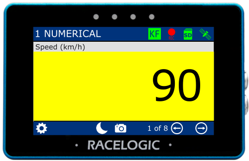
- 1 NUMERICAL
- 3 NUMERICAL
- 4 NUMERICAL
- 6 NUMERICAL
- ANALOGUE GAUGE
- G-BALL
- TARGET
- BAR GRAPH
Each display screen contains one or more elements.
Most elements have multiple settings screens. Swipe left or right, or use the navigation buttons, to move between them.
Tap the currently selected option to change a setting.
Tap Exit to return to the display screen.
Display screens use the units defined in the VBOX display settings.
See below for details on each display screen and its available settings.
IMPORTANT
When an SD card is inserted, MFD Touch will retain all settings after each power cycle.
The display elements have parameters from the connected VBOX system or calculated results from the MFD Touch.
Standard parameters are sourced from the default Racelogic CAN output of the VBOX unit.
Deceleration test parameters are typically used for brake testing. Most of these require additional hardware, such as the VBOX Brake Trigger Switch or the VBOX Pedal Force Sensor with Event Marker Interface.
You can assign any available data from the connected VBOX system, as well as calculated results from the MFD Touch.
NOTES
- Available parameters depend on the connected VBOX system and configuration
- Units may vary depending on system settings
- Test parameters are only available when the relevant test is active
The following parameters are available for display:
- Standard Parameters
- System Parameters Deceleration Test Parameters
- Trigger Test Parameters
- Acceleration Test Parameters
NOTE
Some parameters may not be compatible with all element types.
| Standard Parameters | Decel Test Parameters | Accel Test Parameters |
|---|---|---|
|
|
|
PRODUCT LIMITATION
In addition to the parameters in the table above, the following Standard Parameters are displayed when the VBOX Touch MFD App is used with VBOX 4 or VBOX 3i.
- Filename
- Logging Status
- Memory Used (%)
- KF Status
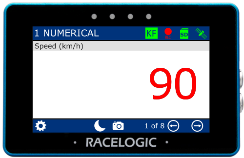
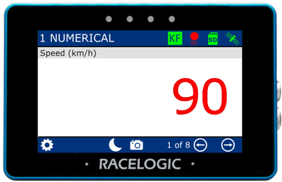
There are 4 different Numerical Display Screens available. They display either 1, 3, 4 or 6 parameters.
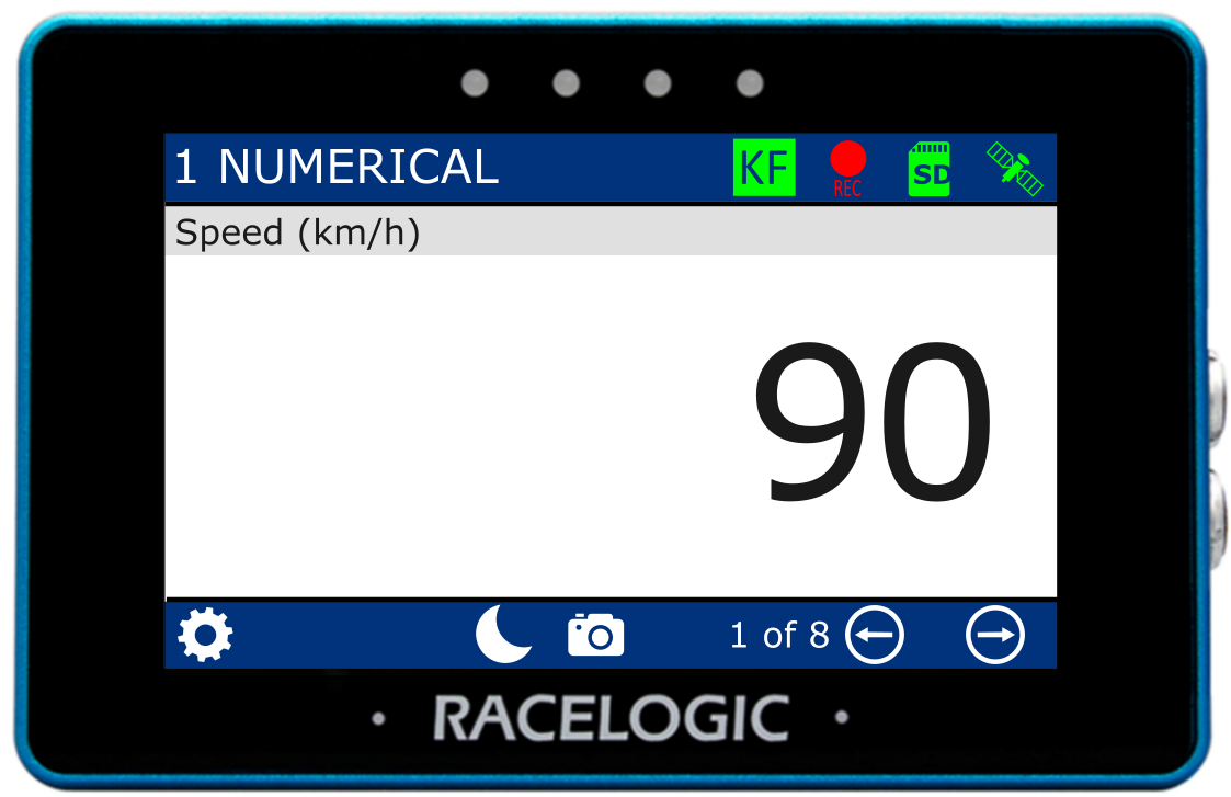
1 Numerical Screen
Element:
Numerical Value
Default Parameter:
- Speed

1 Numerical Screen
Element:
Numerical Value
Default Parameter:
- Speed

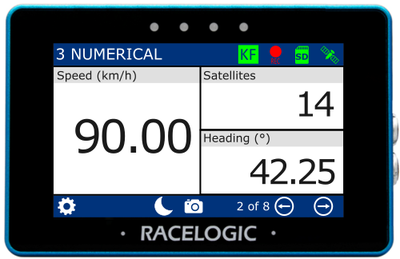
3 Numerical Screen
Elements:
Numerical Value x 3
Default parameters:
- Speed
- Satellites
- Heading
3 Numerical Screen
Elements:
Numerical Value x 3
Default parameters:
- Speed
- Satellites
- Heading

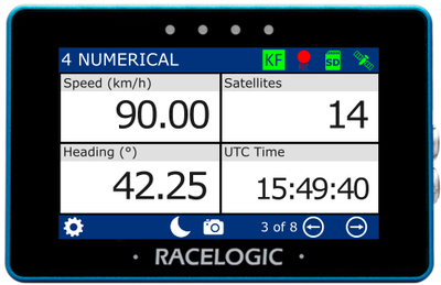
4 Numerical screen
Elements:
Numerical Value x 4
Default parameters:
- Speed
- Satellites
- Heading
- UTC Time
4 Numerical screen
Elements:
Numerical Value x 4
Default parameters:
- Speed
- Satellites
- Heading
- UTC Time

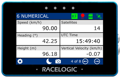
6 Numerical Screen
Elements:
Numerical Value x 6
Default parameters:
- Speed
- Satellites
- Heading
- UTC Time
- Height
- Vertical Velocity
6 Numerical Screen
Elements:
Numerical Value x 6
Default parameters:
- Speed
- Satellites
- Heading
- UTC Time
- Height
- Vertical Velocity
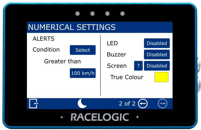
There are two Numerical settings screens: Data and Alerts.
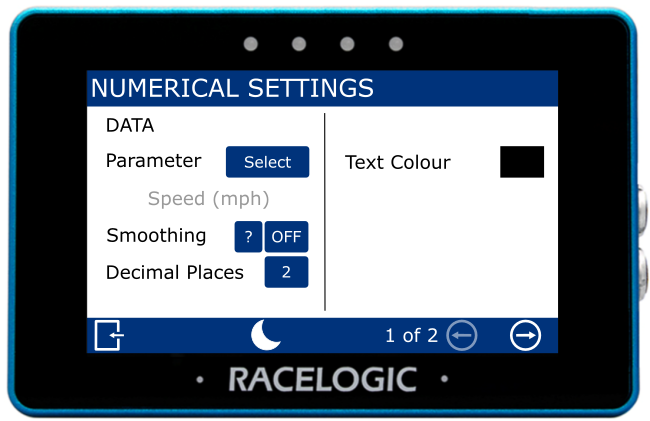
Parameter
This setting defines the parameter used in the element. The current selection is shown below the option.
Tap Select to choose a data source and different parameter.
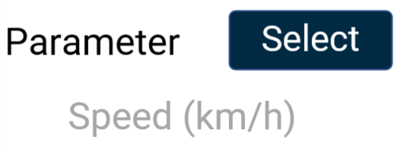
This setting defines the parameter used in the element. The current selection is shown below the option.
Tap Select to choose a data source and different parameter.

NOTE
The currently selected parameter is displayed in grey beneath the option.
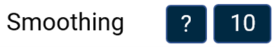
Smoothing
This setting applies smoothing to the live speed values on the display.
Tap the current value (off by default) to enter the number of previous data samples to use for smoothing.
The selected value determines how many previous samples are used to smooth the displayed data. It does not affect performance results or logged data from the connected VBOX system.
Confirm the value to apply the setting, or cancel to return without saving.

NOTES
- The maximum input value is 99.
- Smoothing can introduce a slight delay to the displayed value.
- The setting will be greyed out and disabled if the numerical parameter being configured is UTC Time, Longitude, or Latitude.
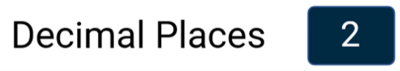
Decimal Places
This setting controls how many decimal places are used to display the selected parameter.
Available options are 0, 1, 2 (default), and 3.
This setting controls how many decimal places are used to display the selected parameter.
Available options are 0, 1, 2 (default), and 3.

NOTE
Integer-only channels, including Satellites, Trigger Test Number, Decel Test Number, and UTC Time, do not have any decimal points.
Text Colour
This setting defines the text colour of the numerical element.
Tap the current colour (black by default) to open the colour selection screen. Use the RGB sliders to adjust the colour; the preview shows the selected colour.
Confirm the selection to apply the new colour, or cancel to return without saving.


NOTES
- Changing the text colour applies to the data text only, and not the parameter label.
- If you enable Night Mode, all user-defined text colours will be reset.
NOTE
The Alert settings will be greyed out and disabled if the numerical parameter that is being configured is UTC Time, Longitude, or Latitude.
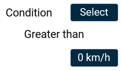
Condition
This setting allows you to define the condition that will trigger the alert.
Tap Select to cycle through the available conditions:
- Equal To
- Not Equal To
- Less Than
- Less Than or Equal To
- Greater Than (default)
- Greater Than or Equal To
- Between
- Not Between
Tap the value field to enter the required value(s) using the on-screen keypad.
Confirm the entry to apply the value, or cancel to return without saving.

LED
This setting controls how the LEDs behave when the configured alert condition is triggered.
Tap the button to cycle through the available options.
The LEDs at the top of the unit will preview the selected behaviour (shown in red).

This setting controls how the LEDs behave when the configured alert condition is triggered.
Tap the button to cycle through the available options.
The LEDs at the top of the unit will preview the selected behaviour (shown in red).

Buzzer
This settings enables an audible alert (beep) when the configured alert condition is triggered.
Tap the button to turn the buzzer alert on or off.

This settings enables an audible alert (beep) when the configured alert condition is triggered.
Tap the button to turn the buzzer alert on or off.

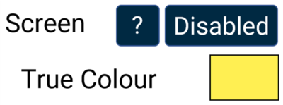
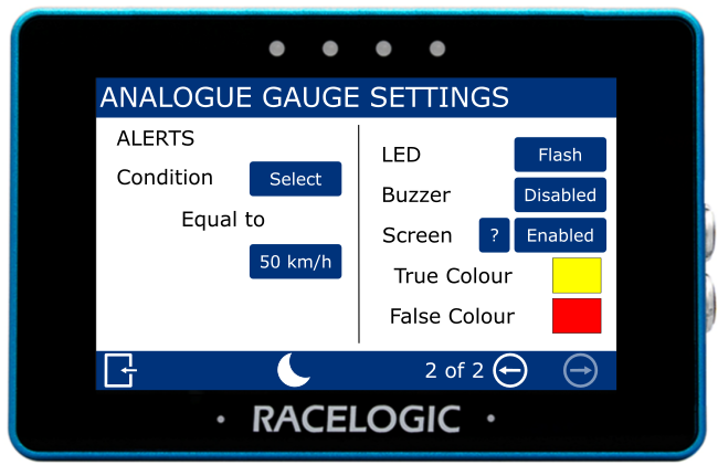
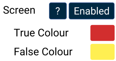
Screen
This setting enables a visual alert when the configured alert condition is triggered.
When the alert is active, the background of the parameter changes colour to highlight the alert.
Tap the current colour (yellow by default) to open the colour selection screen. Use the RGB sliders to adjust the colour; the preview shows the selected colour.
Confirm the selection to apply the new colour, or cancel to return without saving.

NOTE
If you enable Night Mode, this will reset the user-defined alert colour.

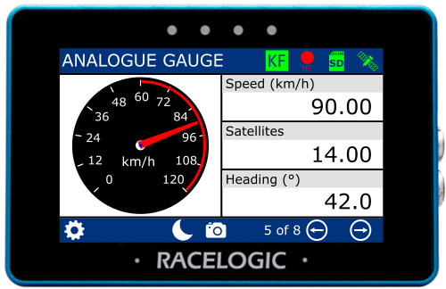
Elements
- Analogue Needle Gauge
- Numerical Value x 3
Default parameters
Gauge:
- Speed
Numerical:
- Speed
- Satellites
- Heading

Elements
- Analogue Needle Gauge
- Numerical Value x 3
Default parameters
Gauge:
- Speed
Numerical:
- Speed
- Satellites
- Heading
The analogue gauge element is located on the left half of the screen and provides a visual representation of the selected parameter.
The 3 numerical elements are on the right half of the screen.
Each element can be configured separately. Refer to the Numerical Settings section for more information about the available settings for these elements.
There are two Analogue Gauge settings screens: Data/Range and Alerts.
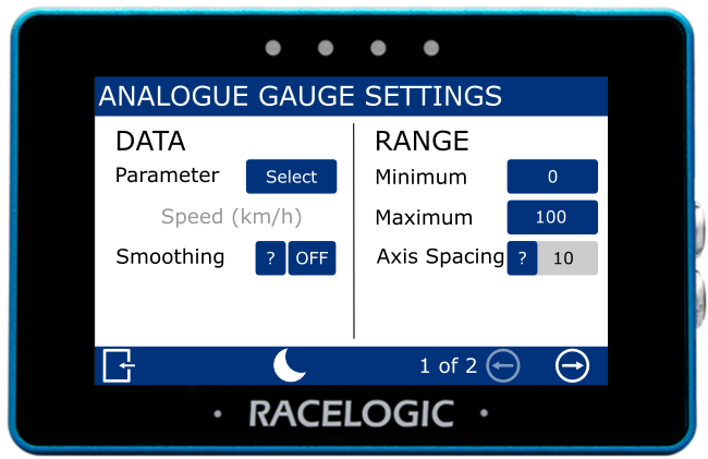
Parameter
This setting defines the parameter used in the element. The current selection is shown below the option.
Tap Select to choose a data source and different parameter.
This setting defines the parameter used in the element. The current selection is shown below the option.
Tap Select to choose a data source and different parameter.
NOTE
The currently selected parameter is displayed in grey beneath the option.
Smoothing
This setting applies smoothing to the live speed values on the display.
Tap the current value (off by default) to enter the number of previous data samples to use for smoothing.
The selected value determines how many previous samples are used to smooth the displayed data. It does not affect performance results or logged data from the connected VBOX system.
Confirm the value to apply the setting, or cancel to return without saving.
NOTES
- The maximum input value is 99.
- Smoothing can introduce a slight delay to the displayed value.
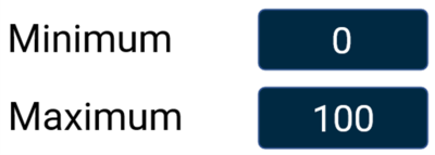
Minimum/Maximum
This setting defines the minimum and maximum values for the axes on the analogue gauge.
Tap the current values (0 and 100 by default) to enter new values using the on-screen keypad.
Confirm the values to apply the setting, or cancel to return without saving.
This setting defines the minimum and maximum values for the axes on the analogue gauge.
Tap the current values (0 and 100 by default) to enter new values using the on-screen keypad.
Confirm the values to apply the setting, or cancel to return without saving.

NOTES
- The maximum input value is 99999.
- The minimum input value is -99999 (when the signed parameter is selected, otherwise 0).
- One decimal place resolution available.
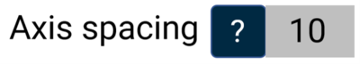
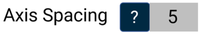
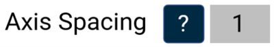
Axis Spacing
This setting defines the spacing between each increment marker on the gauge.
The spacing will adjust automatically based on the selected minimum and maximum range values.
This setting defines the spacing between each increment marker on the gauge.
The spacing will adjust automatically based on the selected minimum and maximum range values.

Condition
This setting allows you to define the condition that will trigger the alert.
Tap Select to cycle through the available conditions:
- Equal To
- Not Equal To
- Less Than
- Less Than or Equal To
- Greater Than (default)
- Greater Than or Equal To
- Between
- Not Between
Tap the value field to enter the required value(s) using the on-screen keypad.
Confirm the entry to apply the value, or cancel to return without saving.
This setting allows you to define the condition that will trigger the alert.
Tap Select to cycle through the available conditions:
- Equal To
- Not Equal To
- Less Than
- Less Than or Equal To
- Greater Than (default)
- Greater Than or Equal To
- Between
- Not Between
Tap the value field to enter the required value(s) using the on-screen keypad.
Confirm the entry to apply the value, or cancel to return without saving.
LED
This setting controls how the LEDs behave when the configured alert condition is triggered.
Tap the button to cycle through the available options.
The LEDs at the top of the unit will preview the selected behaviour (shown in red).
This setting controls how the LEDs behave when the configured alert condition is triggered.
Tap the button to cycle through the available options.
The LEDs at the top of the unit will preview the selected behaviour (shown in red).
Buzzer
This settings enables an audible alert (beep) when the configured alert condition is triggered.
Tap the button to turn the buzzer alert on or off.
This settings enables an audible alert (beep) when the configured alert condition is triggered.
Tap the button to turn the buzzer alert on or off.
Screen
This setting enables a visual alert when the configured alert condition is triggered.
The target zone changes colour based on the alert state:
- False Colour is shown while the condition has not been met
- True Colour is shown when the condition is met
Tap the current colour (yellow and red by default) to open the colour selection screen. Use the RGB sliders to adjust the colours; the preview shows the selected colour.
Confirm the selection to apply the new colour, or cancel to return without saving.
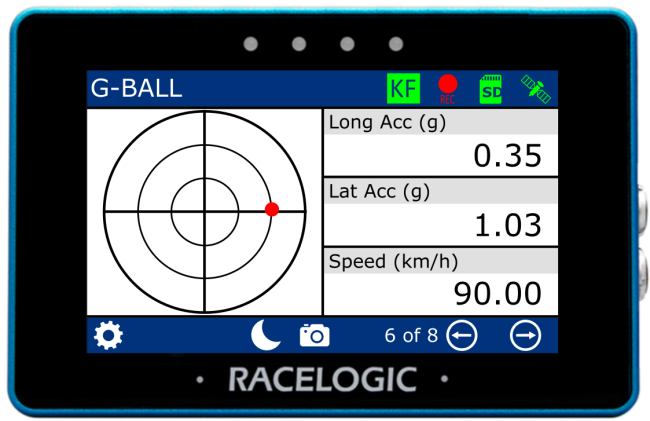
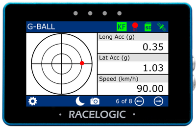
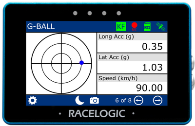
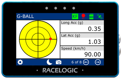
Elements
- G-Ball Gauge
- Numerical Value x 3
Default parameters
Gauge:
- Longitudinal and lateral acceleration
Numerical:
- Longitudinal Acceleration
- Lateral Acceleration
- Speed
Elements
- G-Ball Gauge
- Numerical Value x 3
Default parameters
Gauge:
- Longitudinal and lateral acceleration
Numerical:
- Longitudinal Acceleration
- Lateral Acceleration
- Speed
The G-Ball Gauge element is located on the left half of the screen and provides a visual representation of the longitudinal and lateral acceleration parameters.
The 3 numerical elements are on the right half of the screen.
Each element can be configured separately. Refer to the Numerical Settings section for more information about the available settings for these elements.
There are two G-Ball settings screens: Data/Range and Alerts.
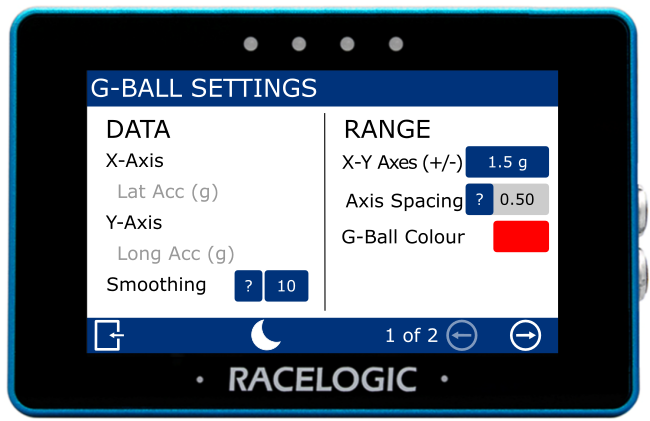
X-Axis/Y-Axis
This area shows which acceleration parameters are assigned to each G-Ball axis:
- X-axis: lateral acceleration
- Y-axis: longitudinal acceleration
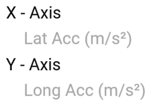
This area shows which acceleration parameters are assigned to each G-Ball axis:
- X-axis: lateral acceleration
- Y-axis: longitudinal acceleration

Smoothing
This setting applies smoothing to the G-Ball data on the display.
Tap the current value (off by default) to enter the number of previous data samples to use for smoothing.
The selected value determines how many previous samples are used to smooth the displayed data. It does not affect performance results or logged data from the connected VBOX system.
Confirm the value to apply the setting, or cancel to return without saving.
NOTES
- The maximum input value is 99.
- Smoothing can introduce a slight delay to the displayed value.
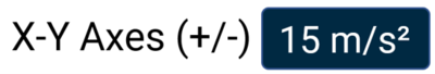
X-Y Axes (+/-)
This setting defines the absolute range for the G-Ball axes.
Tap the value field to enter the required value using the on-screen keypad.
Confirm the value to apply the setting, or cancel to return without saving.

This setting defines the absolute range for the G-Ball axes.
Tap the value field to enter the required value using the on-screen keypad.
Confirm the value to apply the setting, or cancel to return without saving.
NOTES
- The maximum input value is 999.
- The minimum input value is 0.1.
- One decimal place resolution is available to values under 100.
Axis Spacing
This value indicates the spacing between each increment marker on the gauge.
The spacing adjusts automatically based on the X–Y axes range values.

This value indicates the spacing between each increment marker on the gauge.
The spacing adjusts automatically based on the X–Y axes range values.
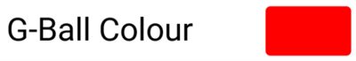
G-Ball Colour
This setting defines the colour of the G-Ball in the gauge element.
Tap the current colour (red by default) to open the colour selection screen. Use the RGB sliders to adjust the colour; the preview shows the selected colour.
Confirm the selection to apply the new colour, or cancel to return without saving.

Alert Channel
This setting defines the alert channel used for the G-Ball.
Tap Select to switch between lateral and longitudinal acceleration.

This setting defines the alert channel used for the G-Ball.
Tap Select to switch between lateral and longitudinal acceleration.

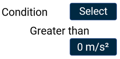
Condition
This setting allows you to define the condition that will trigger the alert.
Tap Select to cycle through the available conditions:
- Equal To
- Not Equal To
- Less Than
- Less Than or Equal To
- Greater Than (default)
- Greater Than or Equal To
- Between
- Not Between
Tap the value field to enter the required value(s) using the on-screen keypad.
Confirm the entry to apply the value, or cancel to return without saving.
LED
This setting controls how the LEDs behave when the configured alert condition is triggered.
Tap the button to cycle through the available options.
The LEDs at the top of the unit will preview the selected behaviour (shown in red).
This setting controls how the LEDs behave when the configured alert condition is triggered.
Tap the button to cycle through the available options.
The LEDs at the top of the unit will preview the selected behaviour (shown in red).
Buzzer
This settings enables an audible alert (beep) when the configured alert condition is triggered.
Tap the button to turn the buzzer alert on or off.
This settings enables an audible alert (beep) when the configured alert condition is triggered.
Tap the button to turn the buzzer alert on or off.
Screen
This setting enables a visual alert when the configured alert condition is triggered.
When active, the background of the parameter changes colour.
Tap the current colour (yellow by default) to open the colour selection screen. Use the RGB sliders to adjust the colour; the preview shows the selected result.
Confirm the selection to apply the new colour, or cancel to return without saving.

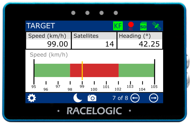
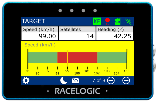
Elements
- Target Gauge
- Numerical Value x 3
Default parameters
Gauge:
- Speed
Numerical:
- Speed
- Satellites
- Heading

Elements
- Target Gauge
- Numerical Value x 3
Default parameters
Gauge:
- Speed
Numerical:
- Speed
- Satellites
- Heading
The G-Ball Gauge element is located on the bottom part of the screen and provides a visual representation of a selected parameter.
The 3 numerical elements are located at the top part of the screen.
Each element can be configured separately. Refer to the Numerical Settings section for more information about the available settings for these elements.
Target Graph Settings
There are two Target Graph settings screens: Data/Range and Colours/Alerts.
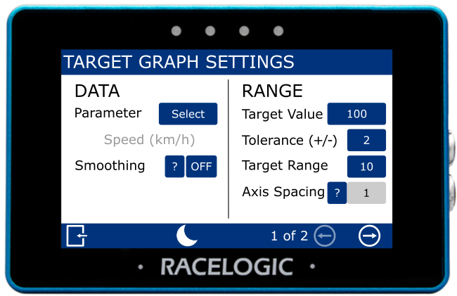
Parameter
This setting defines the parameter used in the element. The current selection is shown below the option.
Tap Select to choose a data source and different parameter.
This setting defines the parameter used in the element. The current selection is shown below the option.
Tap Select to choose a data source and different parameter.
Smoothing
This setting applies smoothing to the G-Ball data on the display.
Tap the current value (off by default) to enter the number of previous data samples to use for smoothing.
The selected value determines how many previous samples are used to smooth the displayed data. It does not affect performance results or logged data from the connected VBOX system.
Confirm the value to apply the setting, or cancel to return without saving.
NOTES
- The maximum input value is 99.
- Smoothing can introduce a slight delay to the displayed value.
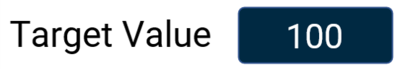
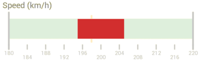
Target Value
This setting defines the target value shown at the centre of the gauge.
Tap the value field (240 by default) to enter a new value using the on-screen keypad.
Confirm the value to apply the setting, or cancel to return without saving.

This setting defines the target value shown at the centre of the gauge.
Tap the value field (240 by default) to enter a new value using the on-screen keypad.
Confirm the value to apply the setting, or cancel to return without saving.
NOTES
- The maximum input value is 99999.
- The minimum input value is -99999 (when the signed parameter is selected, otherwise 0).
- One decimal place resolution is available to values under 10000.
Tolerance (+/-)
This setting defines the tolerance (target zone) on either side of the target value.
Tap the value field (2 by default) to enter a new value using the on-screen keypad.
The tolerance value determines the range around the target value. For example, a target value of 100 with a tolerance of ±2 creates a target zone between 98 and 102.
The colour of the target zone can be configured in the Colours settings (red by default).
Confirm the value to apply the setting, or cancel to return without saving.

NOTES
- The maximum input value is 9999.
- The minimum input value is 0.1.
- One decimal place resolution is available to values under 1000.
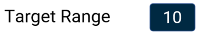
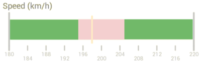
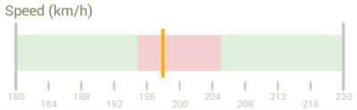
Target Range
This setting defines the range of the background bar around the target value.
Tap the value field (10 by default) to enter a new value using the on-screen keypad.
The range value determines how far the bar extends either side of the target value. For example, a target value of 100 with a range of 10 creates a bar between 95 and 105.
The bar colour can be configured in the Colours settings (green by default).
Confirm the value to apply the setting, or cancel to return without saving.
NOTES
- The maximum input value is 9999.
- The minimum input value is 0.1.
- One decimal place resolution available to values under 1000.
Axis Spacing
This value indicates the spacing between each increment marker on the gauge.
The spacing adjusts automatically based on the target range value.

This value indicates the spacing between each increment marker on the gauge.
The spacing adjusts automatically based on the target range value.
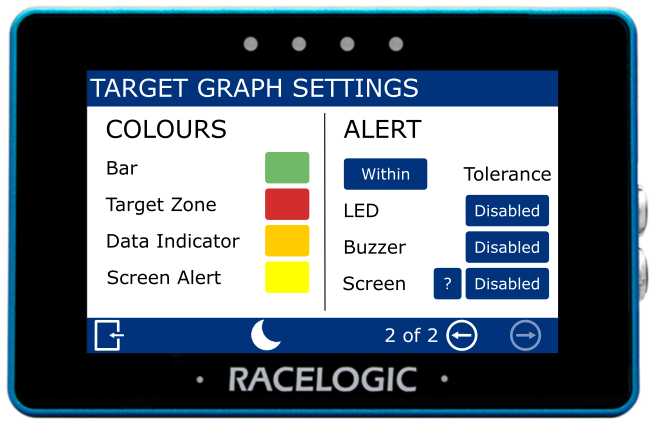
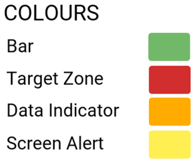
Colours
These settings control the colours used in the Target Graph.
- Bar
Defines the colour of the background bar on the graph. - Target Zone
Defines the colour of the target zone on the graph.
The target zone is configured in the Tolerance setting. - Data Indicator
Defines the colour of the data indicator, which shows the current value on the graph. - Screen Alert
Defines the colour used when the configured alert condition is met.
Change a Colour
Tap the current colour to open the colour selection screen. Use the RGB sliders to adjust the colour; the preview shows the selected result.
Confirm the selection to apply the new colour, or cancel to return without saving.


NOTE
If you enable Night Mode, all user-defined colours will be reset.
Tolerance
This setting determines whether the alert is triggered when the value is Out of (default) or Within the defined target value tolerance.
Tap the button to switch between the available options.

This setting determines whether the alert is triggered when the value is Out of (default) or Within the defined target value tolerance.
Tap the button to switch between the available options.

LED
This setting controls how the LEDs behave when the configured alert condition is triggered.
Tap the button to cycle through the available options.
The LEDs at the top of the unit will preview the selected behaviour (shown in red).
This setting controls how the LEDs behave when the configured alert condition is triggered.
Tap the button to cycle through the available options.
The LEDs at the top of the unit will preview the selected behaviour (shown in red).
Buzzer
This settings enables an audible alert (beep) when the configured alert condition is triggered.
Tap the button to turn the buzzer alert on or off.
This settings enables an audible alert (beep) when the configured alert condition is triggered.
Tap the button to turn the buzzer alert on or off.
Screen
This setting enables a visual alert when the target value tolerance condition is met.
When active, the Target Graph background changes colour to indicate the alert.
Tap the current colour (yellow by default) to open the colour selection screen. Use the RGB sliders to adjust the colour; the preview shows the selected result.
Confirm the selection to apply the new colour, or cancel to return without saving.

NOTES
- The setting will be greyed out and disabled if the numerical parameter you are configuring is UTC Time, Longitude or Latitude.
- If you enable Night Mode, any user-defined alert colours will be reset.
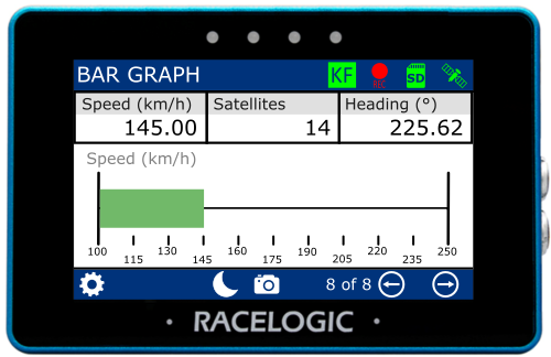
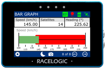
Elements
- Bar Graph gauge
- Numerical Value x 3
Default parameters
Gauge:
- Speed
Numerical:
- Speed
- Satellites
- Heading

Elements
- Bar Graph gauge
- Numerical Value x 3
Default parameters
Gauge:
- Speed
Numerical:
- Speed
- Satellites
- Heading
The Bar Graph Gauge element is located on the bottom part of the screen and provides a visual representation of a selected parameter.
The 3 numerical elements are located at the top part of the screen.
Each element can be configured separately.
Refer to the Numerical Screens section for more information about the available settings for these elements.
There are two Bar Graph settings screens: Data/Range and Alerts.
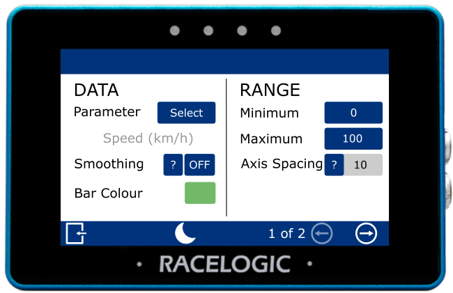
Parameter
This setting defines the parameter used in the element. The current selection is shown below the option.
Tap Select to choose a data source and different parameter.
This setting defines the parameter used in the element. The current selection is shown below the option.
Tap Select to choose a data source and different parameter.
Smoothing
This setting applies smoothing to the G-Ball data on the display.
Tap the current value (off by default) to enter the number of previous data samples to use for smoothing.
The selected value determines how many previous samples are used to smooth the displayed data. It does not affect performance results or logged data from the connected VBOX system.
Confirm the value to apply the setting, or cancel to return without saving.
This setting applies smoothing to the G-Ball data on the display.
Tap the current value (off by default) to enter the number of previous data samples to use for smoothing.
The selected value determines how many previous samples are used to smooth the displayed data. It does not affect performance results or logged data from the connected VBOX system.
Confirm the value to apply the setting, or cancel to return without saving.
NOTES
- The maximum input value is 99.
- Smoothing can introduce a slight delay to the displayed value.
Bar Colour
This setting defines the colour of the bar on the Bar Graph.
Tap the current colour (green by default) to open the colour selection screen. Use the RGB sliders to adjust the colour; the preview shows the selected result.
Confirm the selection to apply the new colour, or cancel to return without saving.

NOTE
If you enable Night Mode, any user-defined bar colours will be reset.
Minimum/Maximum
This setting defines the minimum and maximum values for the axes of the Bar Graph.
Tap the value field to enter a new value using the on-screen keypad.
The default values are 0 (minimum) and 100 (maximum).
Confirm the values to apply the setting, or cancel to return without saving.
This setting defines the minimum and maximum values for the axes of the Bar Graph.
Tap the value field to enter a new value using the on-screen keypad.
The default values are 0 (minimum) and 100 (maximum).
Confirm the values to apply the setting, or cancel to return without saving.
NOTES
- The maximum input value is 99999.
- The minimum input value is -99999 (when a signed parameter is selected, otherwise 0).
- One decimal place resolution available.
Axis Spacing
This value indicates the spacing between each increment marker on the Bar Graph.
The spacing adjusts automatically based on the selected minimum and maximum range values.
This value indicates the spacing between each increment marker on the Bar Graph.
The spacing adjusts automatically based on the selected minimum and maximum range values.
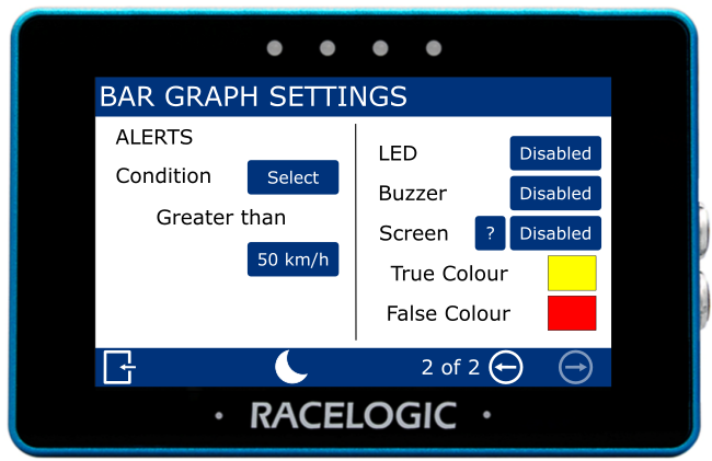
Condition
This setting allows you to define the condition that will trigger the alert.
Tap Select to cycle through the available conditions:
- Equal To
- Not Equal To
- Less Than
- Less Than or Equal To
- Greater Than (default)
- Greater Than or Equal To
- Between
- Not Between
Tap the value field to enter the required value(s) using the on-screen keypad.
Confirm the entry to apply the value, or cancel to return without saving.
NOTE
The setting will be greyed out and disabled if the configured numerical parameter is UTC Time, Longitude or Latitude.
LED
This setting controls how the LEDs behave when the configured alert condition is triggered.
Tap the button to cycle through the available options.
The LEDs at the top of the unit will preview the selected behaviour (shown in red).
This setting controls how the LEDs behave when the configured alert condition is triggered.
Tap the button to cycle through the available options.
The LEDs at the top of the unit will preview the selected behaviour (shown in red).
Buzzer
This settings enables an audible alert (beep) when the configured alert condition is triggered.
Tap the button to turn the buzzer alert on or off.
This settings enables an audible alert (beep) when the configured alert condition is triggered.
Tap the button to turn the buzzer alert on or off.
Screen
This setting enables a target zone that responds to the configured alert condition.
The target zone changes colour based on the alert state:
- False Colour is shown while the condition is not met
- True Colour is shown when the condition is met
Tap the current colours (yellow and red by default) to open the colour selection screens. Use the RGB sliders to adjust the colours; the preview shows the selected colour.
Confirm the selection to apply the new colours, or cancel to return without saving.
NOTE
Enabling Night Mode will reset all user-defined alert colours.