The Pedal Force Event Marker Interface (RLACS292) was designed for use with the Pedal Force Sensor.
The VBOX Pedal Force Event Marker Interface captures the precise moment that any pressure is applied to a brake pedal and outputs a digital signal, which can be used to trigger the start of a test.
It connects inline between the VBOX Brake Pedal Force Sensor (RLACS282) and the Digital input port (D IN) on a VBOX data logger. The interface acts in a similar way to a traditional brake pedal trigger, but with the added benefit of also allowing the measurement of pedal force.
The internal circuitry of the interface constantly monitors the pedal force sensor voltage and adjusts the trigger threshold. This accounts for any fluctuations in pedal force caused by changes in temperature of the sensor itself, preventing incorrect trigger activation.
- Triggers the start of a brake test when pressure is applied to the brake pedal
- Enables measurements of trigger and force with one sensor
- < 5 N Activation
- Connects inline between the VBOX Pedal Force Sensor and a VBOX data logger
- Ideal for brake tests such as SAE J2909 and ECE Regulation 13-H (Brake Assist Systems)
- Easily see when the trigger is activated in VBOX Test Suite
- Wire the Power/Signal In cable on the Pedal Force Event Marker Interface into the 15-way D-sub connector with the Pedal Force Sensor.
IMPORTANT
The Pedal Force Event Marker Interface depends on the signal from the Pedal Force Sensor. You must, therefore, make sure that the corresponding wires from both devices are connected to the same terminals when wiring the two products into the D-sub connector for your VBOX. You can find the wiring information for the Pedal Force Sensor here.
- Connect the D-sub connector to the Analogue Input connector on your VBOX 4.
- Connect the Trigger Out Lemo connector on the Interface unit to the D IN port on your VBOX 4.

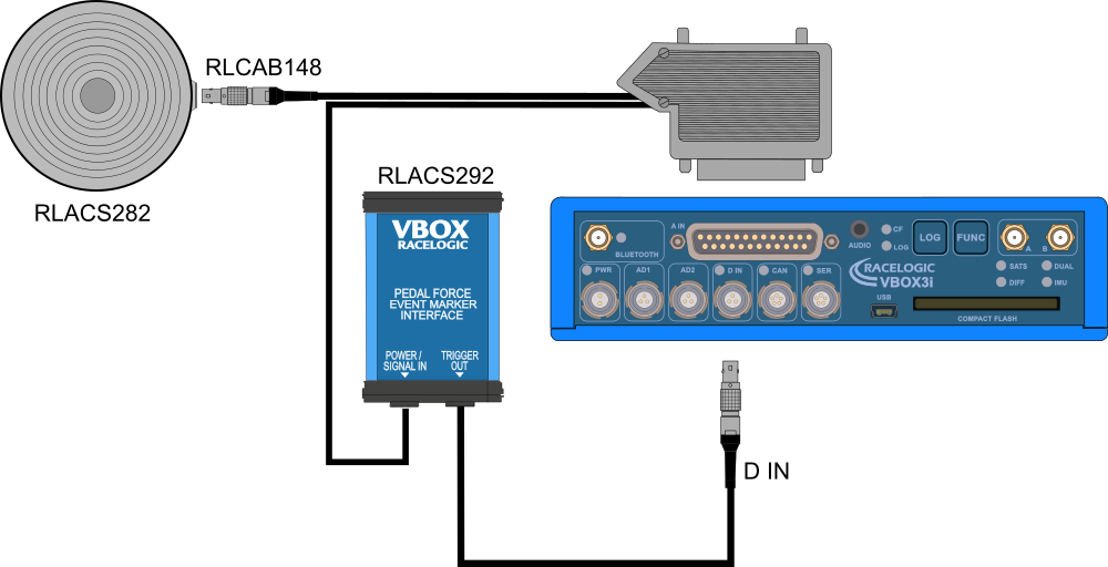
- Wire the Power/Signal In cable on the Pedal Force Event Marker Interface into the 25-way D-sub connector with the Pedal Force Sensor.
IMPORTANT
The Pedal Force Event Marker Interface depends on the signal from the Pedal Force Sensor. You must, therefore, make sure that the corresponding wires from both devices are connected to the same terminals when wiring the two products into the D-sub connector for your VBOX. You can find the wiring information for the Pedal Force Sensor here.
- Connect the D-sub connector to the Analogue Input connector on your VBOX 3i.
- Connect the Trigger Out Lemo connector on the Interface unit to the D IN port on your VBOX 3i.
| Technical | |
|---|---|
| Output Type | Active low open drain with a maximum sink current of 150 mA |
| Activation Force | < 5 N |
| Environmental | |
|---|---|
| Operating Temperature Range | - 40 °C to + 85 °C |
| Power | |
|---|---|
| Power Supply | 4 to 40 V DC @ 10 mA Max |
| Physical | |
|---|---|
| IP Rating | IP 50 |
| Weight | 94 g |
| Input Signal Wire Length | ~ 320 mm |
| Output Signal Wire Length | ~ 265 mm |
| Dimensions | L 66 mm x W 45 mm x H 25 mm |

| Pinouts - Trigger Output (3-way Lemo) | Pin |
|---|---|
| 1 | - |
| 2 | - |
| 3 | O |
| Chassis | - |